The XML Logging file is where the controllers (PLCs) and their associated tags to log are configured. Also, one of two logging modes can be set up; continuous logging (frequency based) or PLC control logging.
for those who are not familiar with XML files; XML is a language that can be read and used by computer software. Specifically, the purpose of XML is to store data in a way that can be easily read by and shared between software applications. XML doesn’t do anything with the data other than store it, like a database.
In an XML file, there are both tags and text. The tags provide the structure to the data. The text in the file that you wish to store is surrounded by these tags, which adhere to specific syntax guidelines.
an XML file is composed of Elements. Elements can have attributes and nested elements.
The configuration in this help illustrates the syntax and structure of the XML logging file and is human readable.
Logging Configuration steps
The configuration is best understood when read in conjunction with the XML logging file.
Note: Controller and PLC are used interchangeably to refer to the programmable logic controller
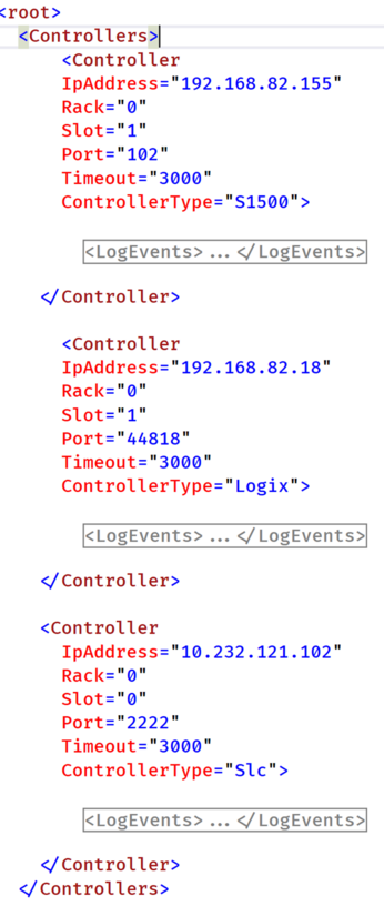
Step 1: Configure the controller
The followings are the supported controller types:
Examples of controller configuration where the IP address; rack, slot, port, connection time out and controller type are set.
Step 2: Understanding events
There are two possible modes for logging: continuous based on a logging frequency or PLC control.
The selection of either of these two modes is discussed in the next step.
PLC Control logging
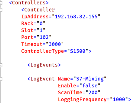
The controller element has nested elements called events.
When logging under PLC control is configured; events can be looked at as an end of stage or cycle in a process. As an example, in a food manufacturing process; there usually is a mixing stage at the end of which we may wish to log the mixing data. And there are also forming, baking and cooling stages.
A controller can have several events configured. Each event in turns has an associated block of data to be logged. Each piece of data is also called a 'Tag’.
Events are especially useful when the logging is under PLC control, i.e., the PLC issues a signal for PlcData to log a block of data.
Another extremely useful role events can play if the data is present momentarily in the PLC where it can be logged hence captured.
PlcData scans the PLC for log signals. The scan is based on the configured ScanTime.
Continuous logging
Continuous logging is based on the logging frequency. When this mode of logging is configured.
Events are useful in defining a block of data to be logged at a frequency.
So different events can be configured for continuous logging but at different frequencies.
Note: The number of events should not exceed the number of parallel connections of the PLC
Step 3 Event logging modes configuration
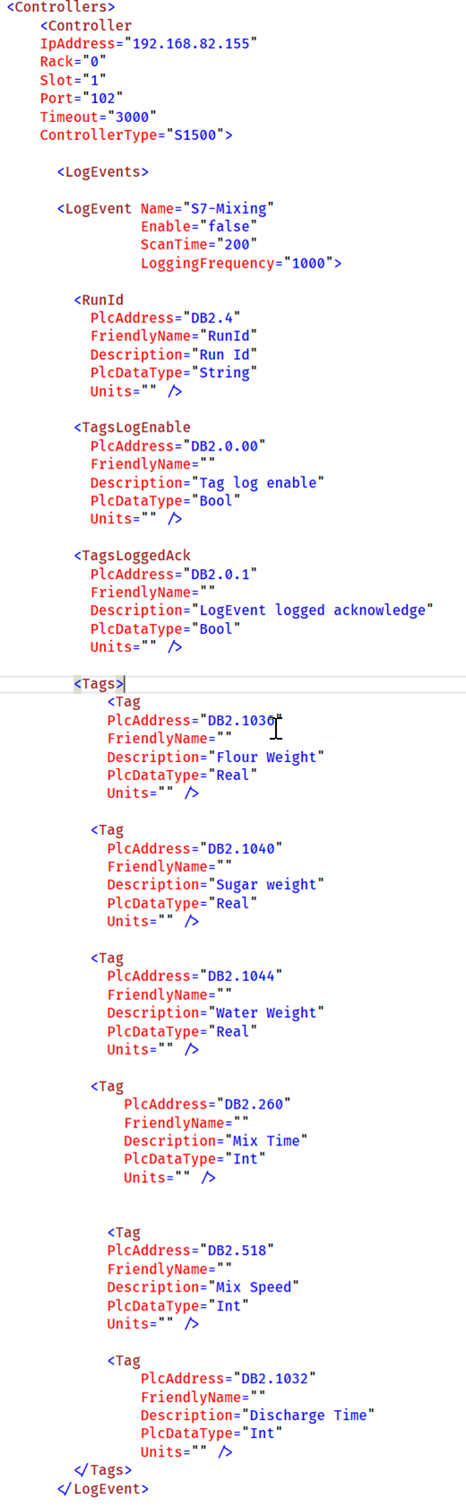
Each event has 4 elements: RunId, TagsLogEnable, TagsLoggedAck and Tags (block of event associated tags to be logged)
RunId
The RunId purpose is to group several events data to indicate the events data is part of the same batch. This is an optional configuration it can be blank.
A batch that has been mixed is then baked, cooled etc. The mixing, baking, and cooling are different events and can have the same RunId to indicate they are part of the same batch.
TagsLogEnable & TagsLoggedAck
The TagsLogEnable Plc Address is what PlcData listens for. When it goes from OFF-To-ON, PlcData logs the block of data associated with the event into the SQL server database.
The TagsLogEnable is optional if the PlcAddress is left blank i.e., PlcAddress=””, then continuous mode is deemed selected and the logging is based on the logging frequency of the event.
If TagsLogEnable has a plc address filled, then the logging is deemed to be PLC controlled and PlcData uses the configured ‘ScanTime’ to listen for logging requests from the PLC.
When PlcData has logged the data, it turns OFF the ‘TagsLogEnable’ flag and sends back a signal to the PLC to indicate the tags have been logged, by turning the ‘TagsLoggedAck’ flag to ON.
Tags
Each event has a block of tags associated with it.
The Tags element has within it several tags elements.
The tags are logged either in continuous or PLC control mode.
PLC - PlcData Handshake
1. Plc sends signal to Log by turning the TagsLogEnable flag to ON.
2. PlcData turns the TagsLoggedAck flag to OFF.
3. PlcData logs the data associated with the event, turns the TagsLogEnable flag to OFF and the TagsLoggedAck flag to ON
4. PlcData checks TagsLogEnable every event scan time. And the cycle repeats from 1.
Step 4 Remote Database Configuration
It is also possible to select a remote database for logging though network issue could hinder logging.
RemoteConnectionString:
This is the connection string of a remote database should remote logging be required.
Normally the system would use a locally installed database server and hence no connection string is needed.
RemoteLoggingEnable:
Set to true to enable remote database logging.
The remote connection string is ignored if this bit is set to false.
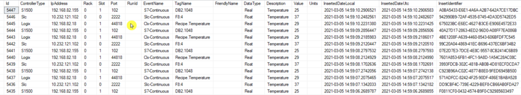
Step 6 Database Logs
Once the XML File has been configured start the service and observe a database "PlcDataDb" has been created after few moments.
If frequency logging had been configured logging starts immediately.
if PLC control has been configured then logging is as at the PLC request.
The date and time of a log are in both UTC and local time.
The insert identifier indicates which group of records have been inserted together into the database